
Project Wrap-Up
IoT-ing a mountain’s hut off-grid solar power system
This is the final wrap-up post for my Eclipse Open IoT Challenge 2.0 project. It will not be the last post about my Solar Monitor since I unfortunately was not able to completely finish my project till the end of the challenge. I’m still waiting for my PCB’s to arrive and also need to finish some software parts. But let’s start from the beginning …
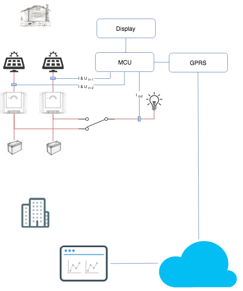
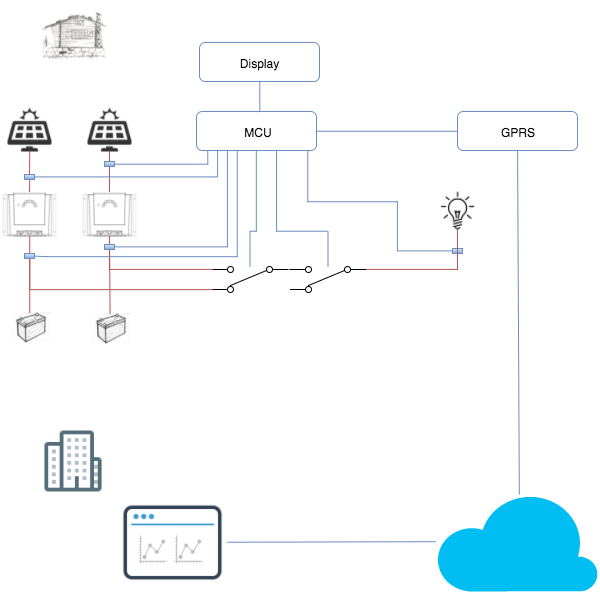
The idea was to add extra sensors and connectivity to the off-grid solar power system of a mountain hut to gain more insides into the generated and used energy.
So as explained in the first steps post I started with boards and shields from my tinkering box and was able to setup a MQTT connection with the Paho client library. After the first steps a saw some issues with the Arduino UNO board and the GPRS Shield as explained in Conclusions after my first steps. So I used my Adafruit voucher and ordered an Adafruit Feather M0 as main MCU and an Adafruit FONA for GPRS. Adafruit FONA provides an nice library with GPRS support and Adafruit also provides compatible MQTT library. But since this an eclipse challenge I implemented the PAHO Network Adapter for the FONA GPRS library and with this was able to use the Paho client library.
Adafruit_FONA sFona(FONA_RST);
Bt_PahoNetworkFona sNetwork(sFona);
MQTT::Client<Bt_PahoNetworkFona, Bt_PahoTimer, 500, 1> sMqttClient(sNetwork);
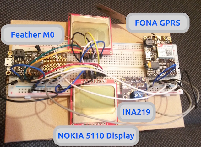
After having prototyped the MQTT connection I also prototyped the dispay and the current sensor. So my protoboard looked like this:
I then started to create the schematic and the board for my solar monitor PBC’s. I had to learn, one time more, that Hardware is Hard, at least for me how has an electrical engineering background, but is only doing software on the job for over 10 years. So I spent hours with detours on how to design the drivers so that I can drive the relays from a MCU pin and then some more hours to actually select the part form the 100’s that do the same. It’s kind of like choosing your javascript library there seem to be hundreds that do the same. So I lost a lot of time and this is why my PCB are not here yet. But at least I have some nice pictures:
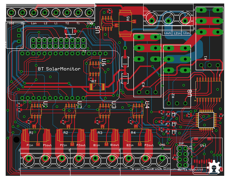
The main board it contains
- 1 Adafruit Feather M0 as main MCU
- 6 INA219 current sensors
- 3 bistable relays (because I decided to also switch the load not just measure)
- 1 ATmega328P as slave MCU (because I run out of IO’s on the main MCU)
- 1 Darlington-Transistor-Arrays to drive the relays
- 1 5V voltage regulator
The main board is connected to a display board:
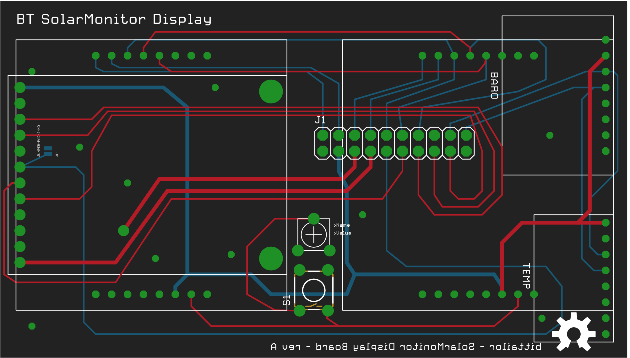
The display board contains
- The Adafruit FONA
- 2 Nokia 5110 displays
- spare connections for a barometric breakout and a temperature breakout
During the creation of the board I made some adoptions to my initial idea. Instead of just measuring I also included some actors. I decided that I would also like to be able to switch off the complete load and switch between the to batteries with the MCU and with this also from remote.
After I sent the Gerbers for the PCB’s to the PCB service I focused back to the software parts.
I used Adafruit.io to create an online dashboard for my solar monitor.
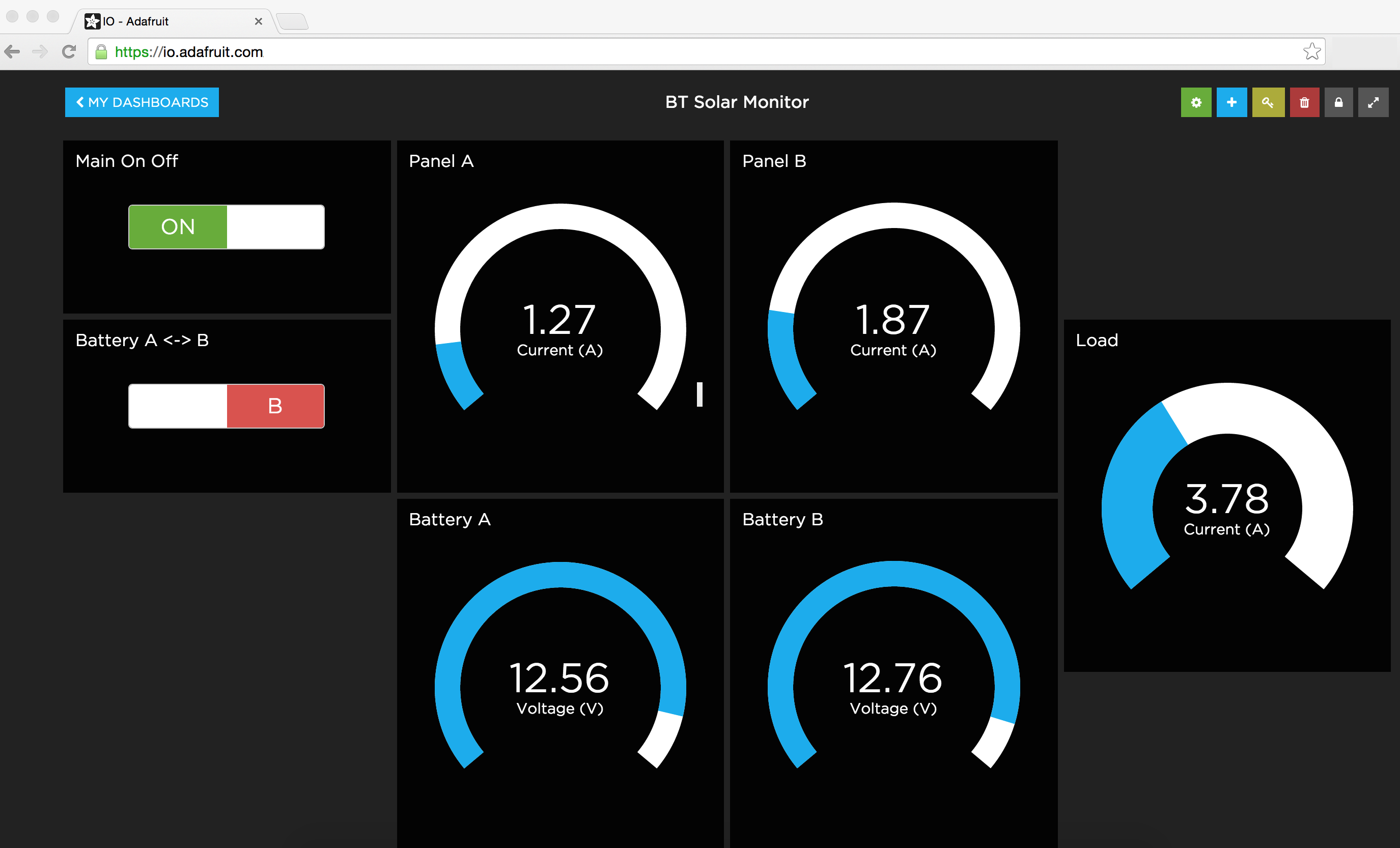
Since Adafruit.io supports MQTT out of the box this was straight forward.
The time for the second Eclipse Open IoT Challenge is up but I will keep going and finish my Solar Monitor.
All the hardware and software parts can be found in this GitHub repository.