Sensor Node PCB
Creating a maker friendly DIY IoT home automation solution
Before starting with the soft parts, I had to tackle the PCB design of the sensor nodes. This since my favorite PCB manufacturer was just about to close for Chinese New Year. I had to place the order before February 7, so that they get manufactured and shipped before the holiday. This week I just received an update:
Your order has been updated to the following status:
Shipped12.Feb - Smart-Prototyping
My sensor nodes PCB’s are on their way.
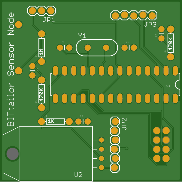
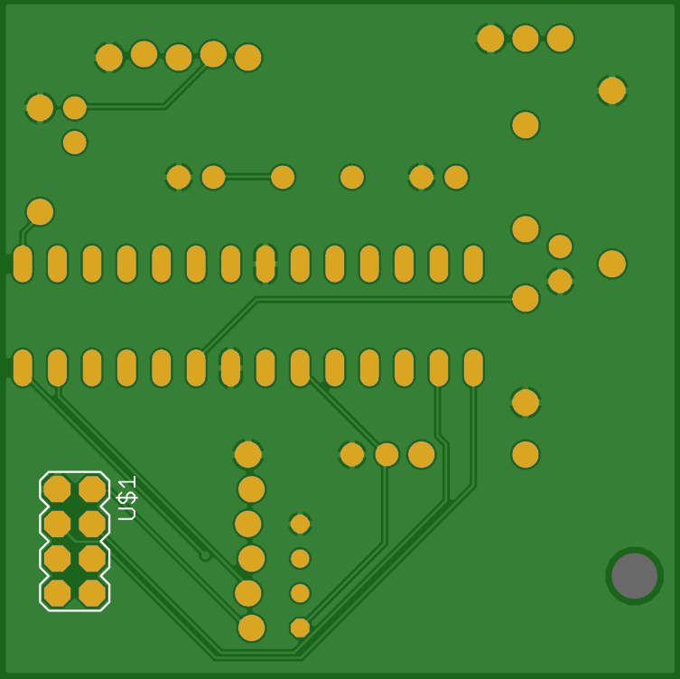
Since I was kind of in a hurry, I used auto routing and did not do a lot of checking before ordering them. Let’s hope they work and that they do not contain too many mistakes that couldn’t be fixed by some extra wiring. Here are the top and bottom views:
Top:
Bottom:
The sensor nodes PCB connects:
- the ATmega328 with the 8MHz crystal oscillator
- the nRF24L01+ transceiver module
- a DHT22 temperature and humidity sensor
- a BMP085 barometric pressure and altitude sensor
- a battery holder for 2 AAA batteries
- a NCP1402 3.3V Step-Up power converter
- and a simple voltage divider to monitor the battery level
I will publish the design after I verified (and probably correted) it with the first batch of PCB’s.
So now I move on to the soft parts.